Installation of TD Belt Type Bucket Elevator
Date:2020-12-21 Source:zk corp Views:
The specific operation methods for the installation of each part of the TD belt type bucket elevator are as follows:
The bucket elevator is divided into multiple parts and shipped. Therefore, according to the specific conditions of the site, refer to the following installation sequence to transport the components to the appropriate location in advance. According to the general installation drawing, refer to the following sequence for installation:
1. According to the drawings, check the foundation bolts.
2. Fix the lower section on the foundation and level the reference surface (upper flange surface).
3. Place the middle standard cabinet on the lower section. An asbestos rope is placed between the casing flanges to seal.
4. Install the access door casing on the upper part of the standard casing. (The detailed cabinet installation sequence is subject to user requirements and general installation drawings).
5. Install the upper section. After the upper section is installed, the centerline of the main shaft should be calibrated so that it is horizontal and parallel to the centerline of the lower shaft. Under normal circumstances, the drive device will be integrated with the upper section before shipment. In order to avoid damage and movement caused by collision with other objects during transportation, after the equipment arrives at the installation site, it is necessary to check whether the drive device is installed in place and start the motor. Check the direction of rotation and confirm that it is correct.
6. After the cabinet is installed and calibrated, it is necessary to use surrounding buildings to strengthen the overhaul platform according to local conditions to reduce vibration and make the equipment run more smoothly.
7. Install traction parts such as lifting belts and hoppers, first install the hopper on the tape, introduce the traction parts into the case from the middle casing (overhaul), hoist from the feed side, connect the tape with the conveyor belt joint until the assembly is complete.
7.1. The installation and fixing of the lifting belt and hopper are shown in the figure below:
The specific operation method of hopper installation is as follows:
(a) Put the hopper, lifting belt, spring washer, nut, etc. together at the bottom, and tighten the nut.
(b) The lifting belt is hoisted from the assembly section to the driving drum, and after passing the drum, it is put down, and the joint is connected at the tail.
(c) Open the upper shell of the head and tighten it again with the afterburner. The tightening torque should be increased as much as possible without damaging the nut.
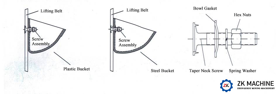
Figure 7-1 Installation diagram of lifting belt and hopper
(d) The belt hoist should be installed in the hopper after the head is connected, but do not install continuously, because the crank will be more and more laborious. The hoppers can be installed at intervals, and the number of hoppers in the rising section and the falling section are as close as possible. The hopper nut must be tightened.
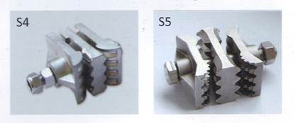
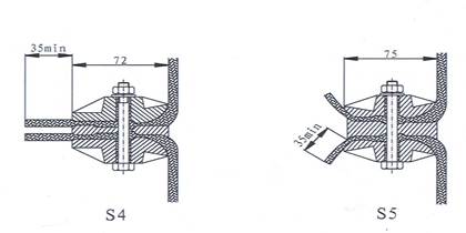
7.2. The tape joint method is shown in the figure below:
Common lifting belt connector models and leather lifting belt joint requirements are as follows:
8. After the hopper and the hoisting belt are installed, the cranking car runs for a week, and the trial operation can be performed only when there is no collision.
9. Installation should comply with the basic requirements.
9.1 The foundation of the hoist must be sufficiently stable, and the supporting surface of the lower section should be in a horizontal position. The relative position of each component should be correct.
9.2 The flange surface of the middle cabinet of each section must be neat and there should be no obvious dislocation. Sealing gaskets are allowed to be used in the connection between the middle casing to ensure the sealing between the casings and the levelness of the flange surface.
9.3 The center lines of all enclosures should be on the same vertical plane. After the cabinet is assembled, use a plumb line (H<40M) or theodolite to measure, and the cumulative deviation does not exceed the value specified in (Table 9.3-1).
Table 9.3-1
|
Measuring part |
Allowable deviation (mm) |
|
H≤40m |
|
|
Deviation of spindle parallel plane and vertical plane |
8 |
|
Deviation between spindle vertical plane and vertical plane |
5 |
9.5 After the drive device is installed, the coaxiality between the center line of the motor and the reducer on the drive device should be less than 1mm.9.4 The parallelism of the main shaft of the hoist drive drum to the horizontal plane is 1/1000.
9.6 Before the conveyor belt joint is connected, the lower roller should be moved to the uppermost position of the tensioning stroke. After the installation is completed, the tensioning device is used to obtain the tension of the belt during normal operation. Tighten the fixing bolts. The parallelism of the reversing roller shaft to the horizontal plane is 1/1000.
9.7 The conveyor belt joint must be perpendicular to the conveyor belt. The error between the joint edge at the edge of the conveyor belt and the vertical line of the conveyor belt shall not be greater than 0.2% of the bandwidth, and the misalignment at both ends of the conveyor belt joint should be less than 2mm.
9.8 After the traction parts are installed and adjusted, the remaining stroke of the reversing drum should be greater than 50% of the full stroke.