Adjustment Method of Rotary Kiln Supporting Device
Date:2020-11-10 Source:zk corp Views:
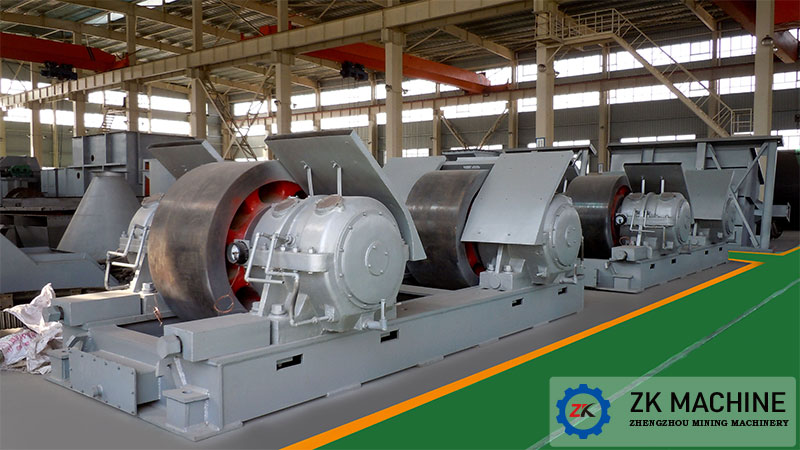
Rotary Kiln Support Device
The supporting roller device bears the weight of the entire rotating part (including the cylinder, lining bricks, large gear ring, tyre, heat exchange device in the kiln, materials, etc.), and can make the drum and tyre rotate smoothly on the supporting roller.
Because the rotary kiln is installed obliquely, the axial force is generated by its own weight and friction, and additional axial force is generated due to the non-parallel axis of the tire belt and the supporting roller. The axial position of the cylinder is difficult to fix, and the cylinder should be allowed to move back and forth in the axial direction. In addition, in order to make the working surfaces of the supporting wheels and tyres with different widths wear evenly, the cylinder is also required to be able to move axially.
In the production process, according to the experience of maintaining the rotary kiln, to ensure the long-term safe operation of the rotary kiln mechanical equipment, the key issue is to adjust the supporting roller.
Purpose of adjusting the supporting roller:
(1) Maintain the linearity of the rotary kiln axis;
(2) Ensure that the kiln body can move back and forth normally along the axial direction;
(3) Each gear supporting roller can evenly bear the cylinder load.
Method of adjusting the supporting roller:
The projection of the roller axis and the kiln axis on the vertical plane is not parallel called tilt, and the projection on the inclined plane of the kiln body installation is not parallel called skew.
When the ordinary retaining wheel is set, the kiln body must be moved upward by the skew of the axis of the supporting roller relative to the tyre. When the upward force is greater than the sliding component of the kiln body weight, the kiln body can move upward; otherwise, try the kiln body. Decline. In the case of thrust and hydraulic gear wheels, it is required that the axis of the supporting wheel be parallel to the axis of the tire belt.

The principle of the driving force generated by the tilting of the supporting wheel is shown in Figure 1. At the contact point between the supporting wheel and the tyre, since the axis of the supporting wheel is fixed, the speed direction is U_t and the circumferential speed of the tyre is U_r. The difference between the directions of U_r and U_t results in the movement speed U_c of the tyre and the corresponding movement force. It can be seen that the magnitude of the channeling force increases or decreases with the tilt angle ξ.
In order to obtain the upward movement force, the relationship between the skew direction of the supporting roller and the rotation direction of the kiln is shown in Figure 2.
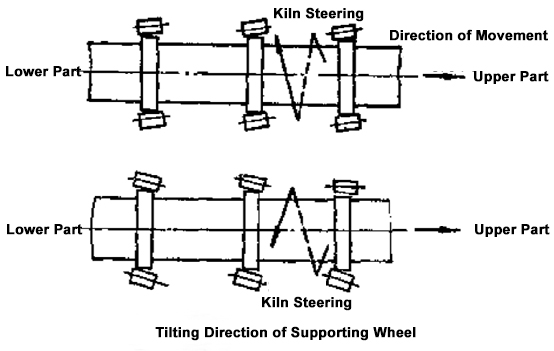
The skew angle of the supporting roller is generally not more than 0°30'. The upward movement force obtained should be slightly greater than the downward force of the kiln body. During the operation of the kiln, the tyre should be in a state of frequent upward movement, that is, the upward kiln. In order to make the kiln body slide down, a small amount of oil can be applied to the surface of the supporting roller with greater force to reduce the friction coefficient. Generally, the kiln body can be moved back and forth 1 to 2 times per shift.