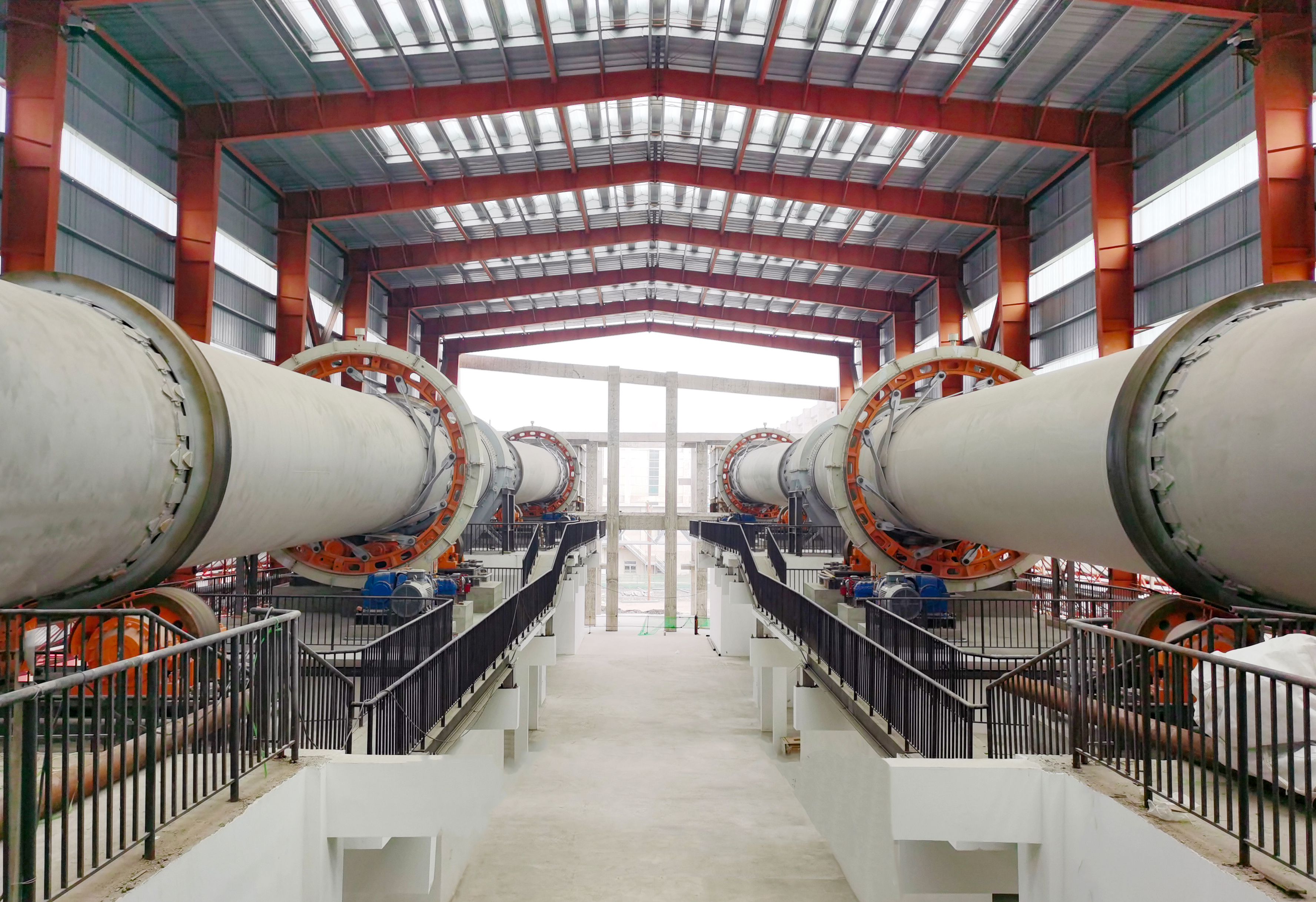
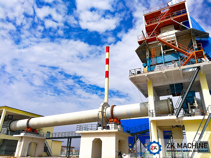
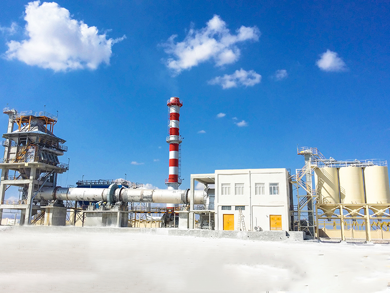
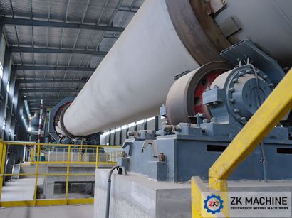
Installation of large ring gear and transmission device
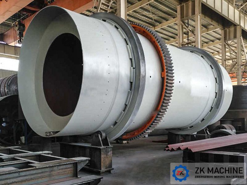
The ring gear is processed from casting steel billet. In the production process, it often appears deformation after processing due to the heat treatment which is not proper. For this reason, the ring gear on the ground should be set up before installing, check the deformation, adjust according to the deformation, and then for hoisting use after it is qualified.
One. The preparation before lifting large ring gear.
1. According to direction and group, using special bolts to put the spring plate on the cleaned, inspecting qualified ring gear or adjusting them ;
2. Before the garter spring plate with the large ring gear bolts, 0.3mm gasket should be inserted between the bolt and spring washer end plate yoke plate.Then tighten the nut, slotting nut grooves along bolt drilling, penetrating cotter pin, and finally remove the gasket.
3. Using 8 # wire to put the spring in a free state on the ring gear in the correct direction ;
4. Checking the cylinder and the spring plate-based site whether having longitudinal welding, if existing, it must be polished smoothly, the weld should not exceed the cylinder surface. Grinding weld length should be greater than the width of the spring about 100mm.
Two. The large ring gear's hoisting
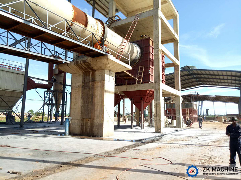
1. Using the crane to hoist the second half of the circle, which is put on the kiln's cylinder to draw the large ring gear transverse center line,then using steel wire rope to tie it on the kiln's cylinder.
2. Using hoisting machine to rotary the kiln 's cylinder by steel wire rope, which could make the half of the ring gear on the top of the kiln's cylinder to move on the directly below position. The crosstie should be set under the ring gear. Let half of the ring gear to fall on the crossite when the wire rope bundled is removed.
3. Lifting the other half of the ring gear that is set on the front half of the upper ring gear according to the group to sign buckle to the coupled mark.
4. Uppper and lower ring gear are justified, then tightened by corresponded bolts.
5. Removing the iron wire like bundled spring, attaching the spring plate to the cylinder;
6. Using lifting jack to adjust lateral center position of the large ring gear to the ring's lateral center position on the kiln's cylinder.
Three. The large ring gear's alignment
Alignment is to find the axial and radial deflection of large ring gear, and making big adjustment to let the axial and radial deflection of large ring gear within the specifications.
1. The technical requirements
①The circular pirch's deviation of large ring gear's interface could not exceed 01.005M(M—modulus)
②The ovality of large ring gear should not exceed 0.004D(D—large ring gear's pitch circle diameter)
③Ring gear group after two and a half ring junction should closely fit with 0.04m feeler, into the surrounding area no larger than 1/5, into the depth of not more than 10mm;
④Large ring gear's radial deviation ≯1.5mm;
⑤Large ring gear's axial deviation ≯1mm;
⑥The position of transverse center line between large ring gear and the adjacent tyre ≯3mm.
2. The method and procedure of large ring gear's alignment.Two types: One type is using split to adjust the framework, radial adjustment and axial adjustment tools are produced separately. Another type is making adjustable stages combining radial adjustmen and axial adjustment tools.The method and procedure of fraemework's alignment by split.
①Using steel tape and scribing compass to separate the large ring gear into eight parts, meanwhile attached marks.
②At each divided point, a radial adjustment bracket is put between the big ring gear and kiln cylinder, the bracket is put over the top of the spring plate, which is aslo welded on the kiln cylinder, the lifting jack is put on the plate between the bracket's riser, bearing against the inner diameter of the ring gear wheels;The bracket adjusting the axial deflection of large ring gear is set on each side of the large ring gear wheels, which is welded with the kiln's cylinder.The inner wall of the two brackets have the distance about 20-30mm fromthe inner circumference of large ring gear.
③Using radial adjustment bracket to adjust the tradial position of large ring gear. Using lifting jack to do axial bolt adjustment of large ring gear.
④A dial gauge gear is placed beneath the large ring gear to measure the radial runout of large ring gear.
⑤A dial gauge gear is placed on both sides of the ring gear to measure the axial runout of the ring gear.
⑥Using hoister to rotate the koln's cylinder by pulley block, observing the radial and axial runout of large ring gear on each divided point, and making the record.
⑦According to the record, using lifitng jack and block screw to adjust the position of large gear ring until the regulatory requirements are meet.
3. The methods and procedures of alignment by adjusting and assembling the bracket:
①The large ring gear is circumferentially divided into four or eight parts,drawn the aliquot mark on the large ring gear.
②According to the circumferentially four or eight equal parts, the adjustable bracket is set on the inner diameter of large ring gear and between the kiln cylinder, then welding the adjustable bracket and kiln cylinder.
③Using radial adjustment bolts to adjust ring gear's radial runout; And using axial adjustment bolts to adjust the ring gear 's axial runout.
The following procedures and methods are similar with the alignment methods that useing split to adjust brackets.
Four. The riveting of large ring gear
The alignment of large ring gear. The riveting can be carried out after qualified examination.
1. The spring plate is closed to and welded on the cylinder.Using corresponding jackhammer driil a hole, one bolt is put into a hole, which is tightened later. After drilling, make reexamination. Rotating the cylinder and checking ring gear's runout that is done again to meet the requirements if runout is abnormal.
2. Using reamer to do the reaming, the processing deviation of bore diametr is above 1mm,a bolt is removed and a hole is reamed when reaming. After reaming. a bolt is put into the holr and tightened.
3. Riveting. Rivets' heating temperature should be controlled at 1000-1100 ℃, namely rivets are pale yellow.Oxide coating is knocked away before rivets are put into the hole.Rivet pole is filled with nail holes, the nail heads are checked by with a small mallet's percussion, any beat should not exist. Visual inspection should comply with the "Steel Construction and acceptance specification. "
Five. Driving pinion's installation
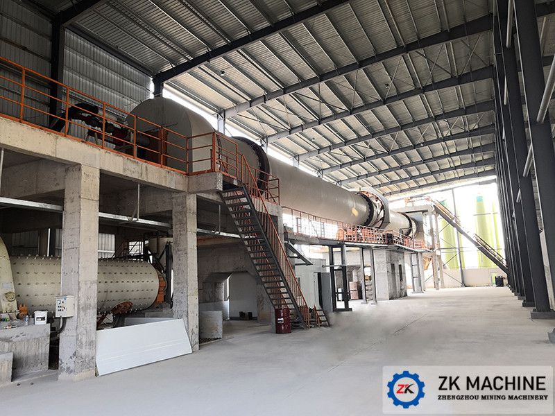
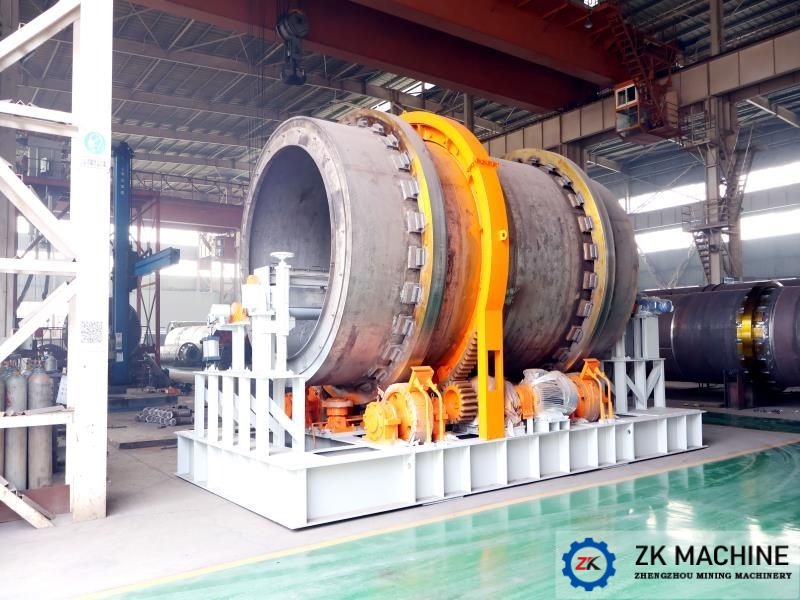
1. The longitudinal centerline of the rotary kiln and the large ring roller's adjacent transverse centerline are regarded as baseline. Using steel tape, steel ruler,scribing compass etc to draw vertical, horizontal centerline of pinion, pinion bearing, main gear, main motor according to the dimensions given in the figure. At the same time, drawing vertical, horizontal centerline of the auxiliary gear and motor.
2. According to their vertical, horizontal centerline,checking the position of the foot,then determining the position of the horn.
3. Cement mortar pier is set on the position of the detrmined horn.
4. When the mortar pier's strength is more than 70%, the cleaned well and satisfactory pinion bearing seat that have enough lubricating grease and pinion gear are put into the proper place, anchor bolts are put on later.
5. The pinion's roughly alignment: Using lifting jack, hand hammers, crowbars, horn, etc to adjust the height of the pinion's center position slope. Making the pinion gear to achieve:
① The pinion's transverse center and ring gear's transverse center are parallel and have a certain distance. The distance is the thermal expansion between the cylinder on the ring gear and base tires;
② Checking the slope on the pinion shaft through taper gauge and party level;
③ Using Square ruler, steel ruler, plumb bob to check the center position of the pinion, the pinion's axial centerline by center label plate and the drawn center line.Axial centerline of the pinion should be parallel to the longitudinal center line of the kiln, the deviation should not be greater than 2mm.
6. The grouting and maintenance of the pinion bearing bolt.
7. The pinion's secondary alignment:
① Using feeler gauge and lead extrusion to measure the headspace or backlash of the gear pair. The tip clearance is about 0.25mn + (2-3mm); mn is the modulus;
②Using coloring method to detect the gear's contact point, the pinion's surface is coated with a thin layer of red lead, open the hoisting machine to rotate the kiln by pulley block, drivening the ring gear.After the combination of ring gear and pinion, ring gear's surface is left contact tracks. The contact point on large or small ring gear's surface is not less than 50, tooth's height is not less than 40 ;
③If the test results do not meet the above requirements, the horn or mobile bearing should be adjusted.
④When the alignment is qualified, making a record and welding the horns together
⑤The surface of the large and small gear is coated with a layer of grease;
⑥Tightening the anchor bolts.(It should be careful to check the level degree of the pinion gear as well as the large or small gear's meshing chagement. If chagement appear, they are timely adjusted.
Six. Installation of main reducer
1. The sizing block is laid on the mortar pier after the conservation's expiry. A flat Horn is under the mortar pier, two is on the top of it.Using the water level and foot tower detect the elevation. The elevation of all Horn reach the design requirements after adjusting, the main reducer should hang on the horn that is put into the anchor bolts later.
2. Checking gear reducer's central location, then adjusted by lifing jack and crowbar.( that is consistent with the center line drawn on the basis ). Using taper gauge, leveller, level gauge to check the Level degree and elevation of the reducer, adjusted by lifting jack, crowbar and sizing block. On the half-coupling of the main reducer's output shaft, two pieces of magnetic dial gague block are set, dial gague is locked. Hands contact with the half couplings on the pinion shaft outer circumference.Rotating the reducer and checking the axiality between reducer and the pinion shaft,requirement:0.2mm。
3. The coupling is circumferentially divided into four parts. Using steel ruler to check the end clearance between the two half coupling, the requirement: According to the drawing requirements, acceptability criterion is saw if the drawing has no requirement.
4. Using lifting Jack, crowbars, hammers, Horn to adjust the reducer to the technical requirements.
5. The grouting of the main reducer's anchor bolt holes.
6. After the expiration of the conservation, the dial gauge and steel ruler should be checked whether changes exist. If exist, using original method to make them into technical requirements.
Seven. The main motor's installation
1. A flat plate and two oblique horn is set on the mortar pier, then operated level according to the elevation
2. Hoisting the main motor on the sizing block, then the anchor bolts are put on.
3. The main motor's alignment has same methods, requirements with the main gear reducer, grouting after inspection and record.
4. The main motor bolt hole's grounting and maintenance.
5. The main motor's secondary alignment.
Eight. Auxiliary transmission device's installation
1. Hoisting the auxiliary reducer on the concrete mortar pier penetrated by the sizing block.
2. Based on the other side of the main reducer input shaft, auxiliary reducer is aligned. The axiality between main reducer input shaft and auxiliary reducer output shaft is 0.2mm, the coupling's end clearance need to meet the requirements in the given drawing sheet.
3. After alignment, making records when the acceptance check is qualified.
4. Anchor Bolts' grouting and conservation.
5. The second alignment.
Nine. Auxiliary motor's installation
1. Hoisting the auxiliary motor on the concrete mortar pier penetrated by the sizing block.
2. Aligning according to the auxiliary reducer's input shaft.The axiality between auxiliary motor's centerline and auxiliary reducer 's centerline is 0.2mm, the coupling's end clearance need to meet the requirements in the given drawing sheet.
3. After alignment, making records when the acceptance check is qualified.
4. Anchor Bolts' grouting and conservation
5. The second alignment.
